3. Mechanical Pipe Bridge Crossing
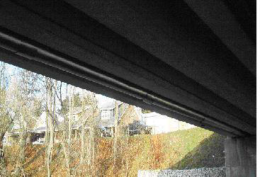
Structural Diagram 1
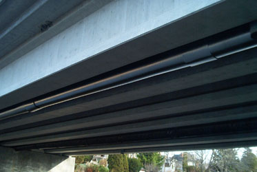
Structural Diagram 2
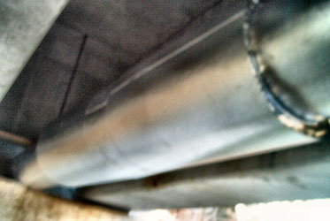
Flange connection (up close)
The Ultimate Solution for Heat-Loss Prevention Systems
Constructed initially of insulated Aluminum jackets, 2" (inch) thickness around iron piping. Electrically heat traced to maintain consistent temperatures for main water lines.
The strength of the load bearing plates and support points are determined by weight of pipe construction, materials and the calculation of the maximum liquid weight traveling through centre core of pipe at all times.
Concentrated loads (i.e. valves, flanges, expansion joints, etc) are supported directly to eliminate high stress concentrations.
When expansion and contraction of a bridge crossing is evident, consideration is given to changes in bridge structure and necessary supports for the system.
Water temperatures are maintained throughout the year. All piping is insulated to meet the fluctuation of extreme temperature conditions, assuming the pipe remains full of flowing water at all times.
Key Benefits
- Includes heat traced wire for main water supply to prevent heat loss
- Insulation system prevents pipes from freezing
- May be constructed as viewed in photos or modified to suit bridge load bearing requirements and restrictions
- Cost effective